
Engineers building new electronic components, IoT devices, or robots are bound to be caught off guard by unexpected project delays while creating the first prototypes. Whereas the advantage of desktop 3D printing is the possibility to create arbitrary shapes with no restrictions on cutting, the process of transforming the CAD designs to the subtractive world reveals the manufacturability gaps that can result in scrap rates up to 30% to 40%.
The key problems in the process are associated with not accounting for the tool deflection, inner radius of tools, and fixture kinematics. Understanding the basics of the subtractive manufacturing process is the key to bridge the gap between digital designs and real parts on the shop floor. The following guide helps engineers to design the right parts for cutting.
What Is CNC Machining and How Do Subtractive Principles Drive Accuracy?
The Computer Numerical Control (CNC) machining technology uses subtractive logic that is deterministic in nature whereby raw stock is attached to a rigid fixture while computer-controlled carbide cutting tools remove excess materials through the Cartesian axis. Contrary to the additive fabrication processes which involve adding volume layer after layer, subtractive cutting maintains the virgin isotropic form of solid raw stock material. This guarantees mechanical rigidity, thermally stable and dimensional accuracy.
For teams transitioning from additive builds to precision engineering, mastering CNC machining basics helps eliminate fundamental assumptions about tool access, spindle travel, and coordinate referencing. Subtractive accuracy relies on a closed-loop system where machine controllers continuously compensate for spindle thermal expansion and ballscrew backlash down to micrometer increments. According to the NIST Smart Manufacturing and Metrology standards, closed-loop toolpath compensation remains a primary requirement for maintaining spatial repeatability across high-speed cutting cycles.
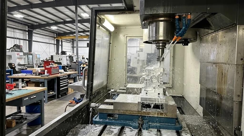
How Does Subtractive Cutting Remove Material Across Complex Geometry?
Subtractive cutting is not grinding but plastic shear deformation within localized areas. During the rotation of cutting tool flutes, the sharp blade bites into the stock causing compressive forces that push the material along primary and secondary shear lines into chips. The control of chip flow and heat generation determines whether the workpiece will meet the drawing specification or distort from excess cutting force.
- Peripheral Profile Milling: The cylindrical surface of an end mill cuts material along the peripheral walls. Tool deflection grows exponentially with overhang distance. Therefore, deep features need to be cut conservatively using stepped passes in order to maintain the required dimensional accuracy.
- Face Milling Operations: Large indexable face mills cut horizontally flat surfaces. This process creates uniform flatness and good datum planes for further machining operations.
- Micro-Drilling and Reaming: Drills create cylindrical holes by cutting on the axis of rotation, while reamers cut fractional layers (≤0.05 mm) to produce accurately sized H7 press-fit bearing bores.
- Turn-Mill Integration: Turn-mill machines rotate the workpiece while simultaneously cutting off-axis geometry with live tools.
Combining Vc spindle surface speed with feed per tooth avoids chatter vibration to ensure that the final product meets desired roughness standards as described by ASME B46.1 surface texture and lay standards.
Which Engineering Materials Match Specific Subtractive Cutting Operations?
Choosing the right material alloy is a trade-off between material thermal conductivity, hardness, work hardening properties, and chip formation. The reference table below shows the general machinability properties for various hardware alloys:
| Material Grade | Machinability Index | Recommended Surface Speed (Vc) | Thermal Sensitivity | Common Hardware Application |
|---|---|---|---|---|
| AL 6061-T6 | 90% (Baseline) | 250–450 m/min | Moderate (Rapid heat dissipation) | Drone arms, IoT enclosures, heat sinks |
| AL 7075-T651 | 70% | 180–300 m/min | Low (High structural rigidity) | Robotics brackets, stress-bearing links |
| SUS 316L | 35% | 60–110 m/min | Severe (High work-hardening rate) | Medical fluidics, marine sensor housings |
| PEEK 450G | 45% | 80–150 m/min | Critical (Risk of internal stress warp) | Insulating blocks, surgical robotic arms |
From the MatWeb material verification databases, tool coatings that have been optimized (TiAlN coating for austenitic steels or bare micro-grain carbide for aluminum) avoid edge build up and ensure dimensional conformity under heavy cutting forces.
Why Do Hardware Prototypes Fail Beginners’ CNC Machining Limitations?
Hardware designers inexperienced with subtractive manufacturing processes sometimes add geometric aspects that violate typical cutting dynamics. Knowledge of these physical constraints prior to file submission to purchasing helps avoid unnecessary engineering changes.
Feature 1: Interior Sharp Corners and Deep Cavity Ratio
Rotational cutting tools cannot create interior sharp corners. The incorporation of interior sharp corner requires the usage of EDM or micro-tooling to achieve the desired result, increasing the time spent on machining dramatically. Typically, the radius of the interior is recommended to be at least 15% larger than the cutting radius to ensure smooth path instead of corner dwelling. Moreover, cavity depth higher than 4× diameter of the cutting tool leads to significant tool deflection and runout.
Feature 2: Cantilever Walls and Insufficient Clamping Land
Thin walls with less than 0.8 mm for aluminum or 1.5 mm for plastic parts tend to deflect due to tool force, resulting in chatter and taper. Also, the design without clamping surfaces will require the development of customized soft jaws to be used during machining.
When Should Teams Transition from Rapid Prototyping to Precision CNC Machining Services?
With a transition from engineering fit form verification through to Environmental Stress Screening (ESS) or Design Verification Testing (DVT), the additive polymers will not be stiff enough or have accurate sealing capabilities.
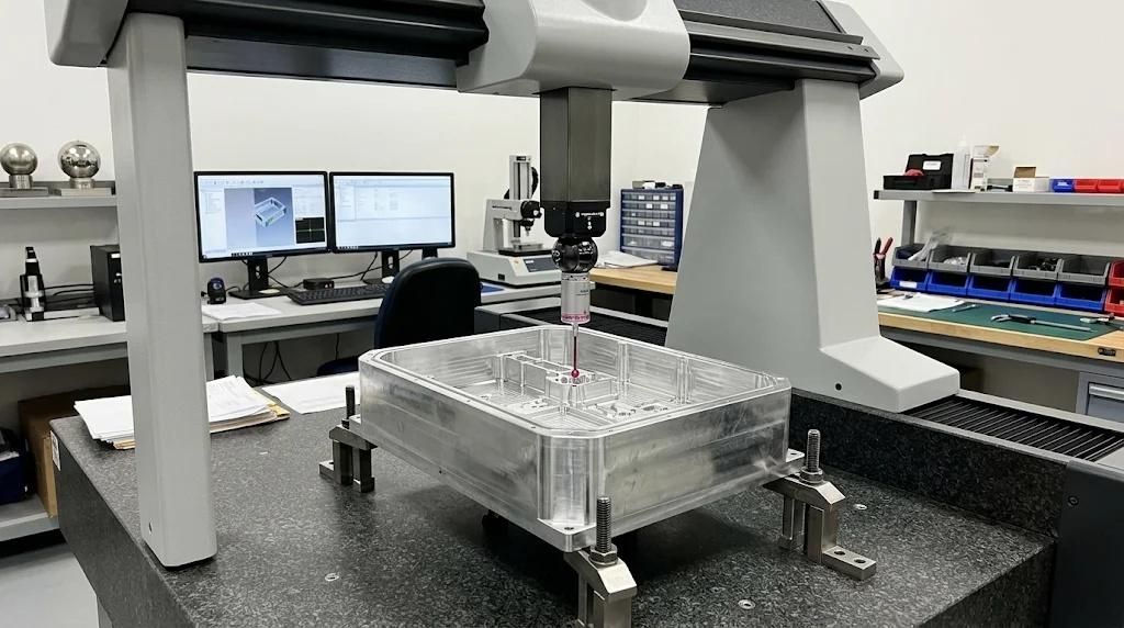
At this stage, partnering with proven precision CNC machining services provides hardware teams with dedicated multi-axis milling, specialized fixture development, and documented coordinate measuring machine (CMM) inspection data. Automated DFM feedback helps identify non-standard hole taps, missing corner fillets, and unmachinable undercuts before stock is cut. According to the ISO 8015 Geometrical Product Specification (GPS) framework, establishing clear datum reference frames during this transition prevents over-tolerancing and keeps piece-part pricing predictable during pre-production runs.
How Can Teams Apply Structured DFM to Minimize Production Scrap?
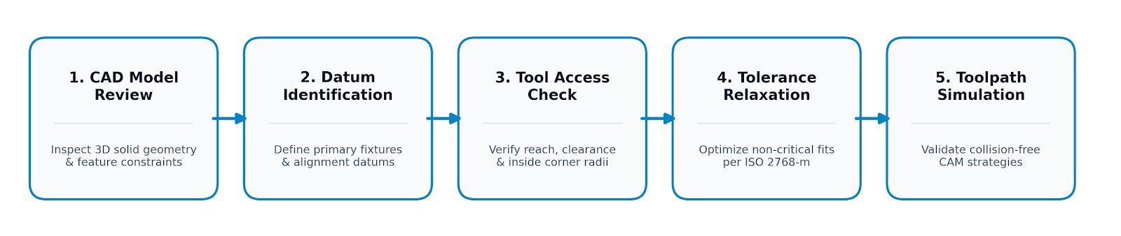
- Standardized Internal Fillets: Specify the standard cutter sizes (for example, R3.0mm or R4.0mm) for internal floor to wall radius to enable optimal machining speed using flat bottom end mills.
- Selective Use of Tight Tolerances: Apply tight tolerances (±0.01mm) only for critical bearing or dowel fits while maintaining the general ISO 2768-m tolerances for other cosmetic surfaces.
- Unification of Setup: Create holes and slots in orthogonal orientation for simultaneous processing in the same setup to avoid error propagation during multiple setups.
Following the above recommendations helps the hardware development team reduce scrap and simplify the CAM programing process while maintaining the efficiency of low-volume production processes.
Conclusion
The creation of parts from CAD models to physical parts depends on the mechanical requirements of the part in addition to the physics of machining. The use of tool geometries, tolerance ladders, and proper alloy based on the environment will help to do away with prototypes that are scrapped during the prototype process. Correct design consideration in the CAD process will lead to good transition of prototypes into manufacturing.
FAQs
Q1: What is the minimum wall thickness that should be used in CNC milled metal parts?
A1: It is recommended to use 0.8 mm as minimum wall thickness for aluminum parts while 1.5 mm is safer for structural requirements. Thin walls will cause chatter and deflection because of heat during tool passes.
Q2: What is the difference between 3 axis machine and 5 axis continuous mill?
A2: 3 axis machines mill parts using x,y,z axes while 5 axis milling rotates in two additional rotational axes.
Q3: What is the best cooling fluid strategy for aerospace alloys?
A3: The best cooling fluid strategy for materials such as titanium or 7075-T6 would be high-pressure through-spindle synthetic coolant since it removes chips quickly, controls thermal growth and increases the lifespan of cutting tools.
Q4: Why does using standard ISO 2768-m tolerance decrease cost?
A4: Standard ISO 2768-m tolerance ensures that there is no micro-finishing pass over any non-critical surfaces, as milling with tight tolerance occurs only on mating surfaces.
Q5: Can engineering plastics such as PEEK be processed with tight tolerances like metals?
A5: Engineering plastics such as PEEK can be manufactured with very tight tolerances up to ±0.01mm if there is sharp carbide tooling, low spindle heat and stress relieving annealing after machining.
Author Bio
The guidelines were written by the precision engineering experts at LS Manufacturing. The company, which is ISO 9001, IATF 16949, ISO 14001, AS9100D, and ISO 13485 accredited precision contract manufacturer, offers automated DFM feedback, precise multi-axis CNC milling and full CMM metrology services to hardware innovators around the world. Engineers who want to mitigate the risks associated with future hardware builds can upload their 3D models to the website to get a manufacturability assessment.