
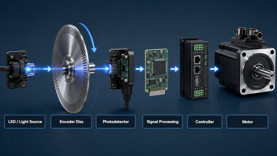
Modern motion-control systems depend on a continuous flow of information between software and hardware. A controller sends a movement command, the motor responds, and an encoder measures what actually happened. The controller can then correct any difference between the target and the real position. Inside many optical encoders, a thin metal disc with precisely arranged slots or patterns plays an important role in generating this feedback. For these detailed components, chemical etching provides a manufacturing option for creating complex patterns in thin metal.
How Optical Encoders Work
An optical encoder converts mechanical motion into an electrical signal that a control system can read.
A typical system includes a light source, an encoder disc, a photodetector, signal-processing electronics, and a controller. The disc rotates with a shaft and contains transparent or open areas arranged in a specific pattern.
As the disc rotates, the pattern changes how light reaches the detector. The sensor converts these changes into electrical pulses or coded signals.
Software can then use this information to calculate position, speed, direction, or movement.
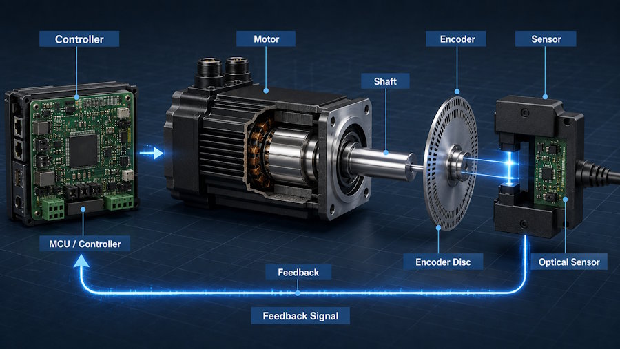
This makes the encoder part of a closed-loop control system:
Command → Motor Movement → Encoder Feedback → Controller Correction
The software may make the decisions, but it depends on reliable physical feedback.
Incremental vs Absolute Encoders
Optical encoders generally fall into two common categories.
Incremental Encoders
Incremental encoders generate pulses as the shaft rotates.
The controller counts these pulses to measure changes in position. Pulse frequency can also be used to calculate rotational speed, while multiple signal channels can help determine direction.
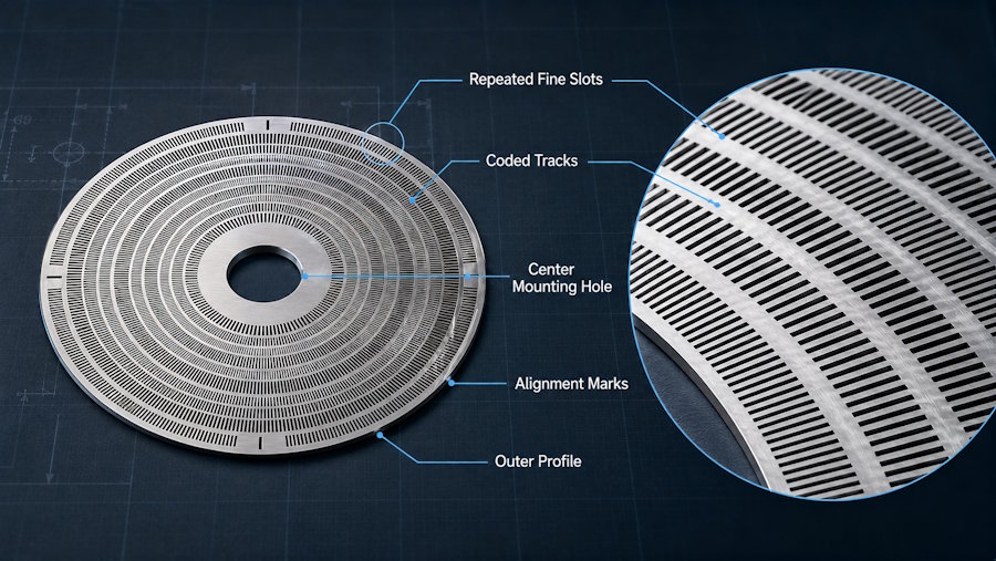
The encoder disc often contains repeated slots arranged around its circumference.
Absolute Encoders
Absolute encoders use a coded pattern that represents a specific shaft position.
Instead of only counting movement from a reference point, the controller can identify the position from the pattern being read.
These discs can require several tracks or more complex coded geometries.
Both types depend on the relationship between the disc pattern, sensor, mechanical mounting, and signal-processing system.
Why Encoder Disc Geometry Matters
An encoder disc may look simple, but several physical details influence how well it integrates with the sensing system.
Important features can include:
- Slot width.
- Slot spacing.
- Number of slots.
- Disc diameter.
- Center hole geometry.
- Pattern concentricity.
- Alignment marks.
- Flatness.
A disc with hundreds of repeated openings creates a different manufacturing challenge from a simple round washer.
Pattern consistency matters because the optical sensor reads changes produced by those openings. However, the encoder disc alone does not determine the final accuracy of the motion-control system.
Sensor quality, shaft alignment, bearings, electronics, signal processing, installation, and software all affect final performance.
How Chemical Etching Creates Encoder Discs
Chemical etching removes selected areas from a metal sheet through a controlled chemical process.
The sheet is coated with a light-sensitive material. Digital artwork defines the required pattern, including slots, mounting holes, alignment features, and the outer profile.
After exposure and development, an etchant removes the unprotected metal. The parts are then cleaned and inspected.
This approach is well suited to encoder discs because multiple repeated slots and other features can be included within the same digital pattern.
The process also avoids a mechanical cutting tool pressing directly against the thin sheet.
Why Etching Fits Precision Motion Components
Several characteristics make chemical etching useful for selected encoder designs.
Repeated Fine Patterns
Optical encoder discs may contain many closely spaced slots.
With photochemical processing, these features are defined through the same artwork rather than being treated as unrelated mechanical cutting operations.
Thin Metal
Encoder discs are often designed as thin components so they can fit inside compact motors, sensors, and control assemblies.
Chemical etching can create complex flat geometry without direct cutting pressure from a tool.
Multiple Features in One Pattern
A single design can include more than the sensing slots.
The same flat part may also contain:
- Mounting holes.
- Alignment features.
- Reference marks.
- Coded tracks.
- Outer profiles.
- Identification details.
Digital Design Changes
Motion-control hardware often changes during development.
An engineer may adjust the number of slots, move an alignment feature, change the disc diameter, or revise a mounting hole.
Because the geometry comes from digital artwork, these changes can often be made without creating a new hard stamping die for every design revision.
This can support prototype development, engineering validation, pilot builds, and product families that use several encoder versions.
From Encoder Signal to Software Control
For developers, the most useful way to understand an encoder is to follow the data.
Physical Rotation → Encoder Disc → Optical Sensor → Digital Signal → MCU or Controller → Motion Algorithm → Motor Correction
The controller can only respond to the signal it receives.
If the mechanical assembly is poorly aligned, the sensor is unstable, or the encoder geometry is unsuitable for the optical system, software may receive imperfect feedback.
This is why motion-control development should not separate software from mechanical design.
The encoder, sensor, controller, actuator, and code must be designed as one feedback system.
Where Optical Encoders Are Used
Optical encoders can appear in many types of equipment.
Industrial robots use position feedback to control joints and axes. Servo motors use encoders to monitor rotation. CNC equipment needs feedback for controlled machine movement.
Other applications can include printers, scanners, cameras, conveyor systems, laboratory equipment, automation systems, and selected medical devices.
The exact encoder design depends on required resolution, speed, environment, mounting space, sensing method, and control architecture.
When Other Manufacturing Methods Make Sense
Chemical etching is not the only way to manufacture encoder components.
CNC machining may be more suitable for thicker mechanical structures or three-dimensional parts. Stamping can be economical for simple designs produced in very high volumes. Laser cutting can be useful for larger flat profiles and some thicker materials.
Chemical etching becomes more attractive when a part is thin, flat, detailed, and contains many repeated openings or coded patterns.
Manufacturing selection should consider material, thickness, feature size, tolerance, volume, flatness, secondary operations, and total cost.
Precision Beyond the Encoder Disc
Motion-control assemblies may also contain other small metal parts.
Shims can control mechanical gaps. Contacts can support grounding or electrical connection. Thin screens can protect sensor openings. Control electronics may also use EMI shielding when electromagnetic compatibility is a concern.
Each component solves a different problem, but they share one requirement: their geometry must work correctly with the surrounding hardware.
Reliable Motion Starts With Reliable Feedback
Precision motion control is a combination of software, electronics, sensing, mechanics, and manufacturing.
Optical encoders help connect physical movement with digital control by converting rotation into information the controller can process.
For thin metal encoder discs with fine slots, coded patterns, and complex flat features, chemical etching offers a practical manufacturing option. It does not determine system accuracy on its own, but it can support the precise physical components that make closed-loop motion control possible.