
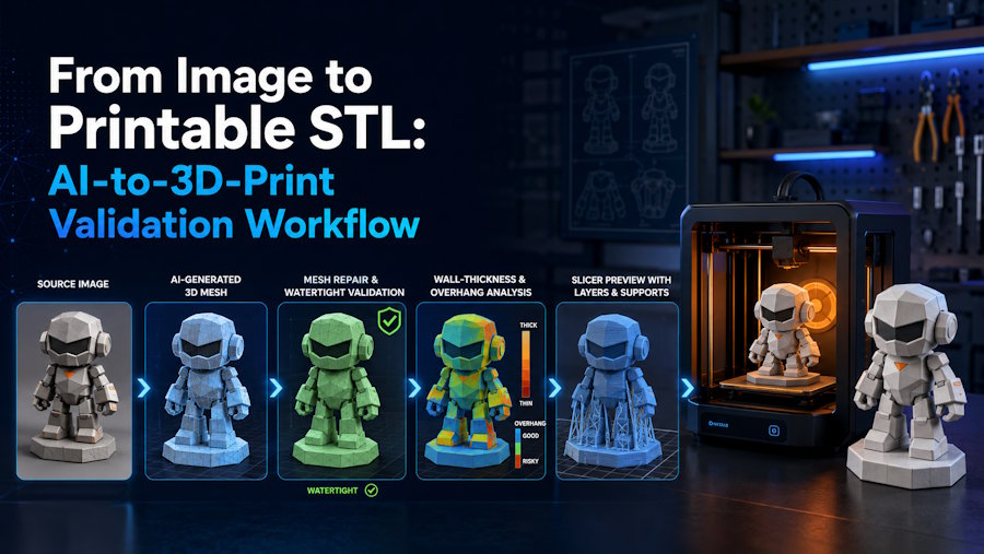
To turn an image into a printable STL with AI, generate a complete 3D mesh, repair the geometry into an intentional solid, export the corrected model, confirm physical scale in the slicer, inspect the sliced layers, and run a representative test print. That is the practical path because exporting an STL only hands off surface geometry. It does not prove that the object is closed, manifold, strong enough at scale, or supportable on the target printer.
The real challenge is not getting from image to mesh. It is getting from mesh to printability. A browser preview can make a model look convincing while still hiding open borders, self-intersections, fragile details, floating parts, bad orientation, or features that disappear once the object is sliced. For that reason, a printable STL is not a file type. It is the result of a validation process.
V2Fun fits the early part of that process by turning a clear image or consistent multi-view references into a 3D starting mesh and supporting STL or 3MF export in an image-to-3D workflow. It is useful when visual form is the main starting point, such as a figurine, bust, ornament, cosplay-prop draft, display object, or early product-form study. It does not replace mesh-repair tools, CAD, slicers, or a physical test print. Those tools still decide whether the generated geometry can survive the chosen process, size, material, and use case.
An STL File Is Not a Printability Test
STL describes an object's surface as a triangle mesh. The Library of Congress STL format description identifies triangular facets as the format's surface representation and notes that STL has no standard way to preserve conventional color, texture, or other appearance data.
In practice, that means three things.
First, the file extension does not prove that the triangles form a valid solid. An STL may contain open borders, non-manifold edges, flipped normals, self-intersections, duplicate faces, internal shells, or disconnected pieces. A slicer may repair some faults automatically, but a silent repair does not prove that the source mesh was correct.
Second, STL does not provide a standardized unit declaration. Export and import software may interpret the same numbers differently. Check the object's bounding dimensions as soon as it enters the slicer. If the scale is wrong, every later decision about thickness and supports will also be wrong.
Third, a valid surface can still describe a poor print. Thin fingers, straps, blades, stems, pegs, embossed text, or narrow contact points may disappear in slicing or break during handling. Orientation may create large overhangs or weak layer direction. The model may also need a base, part split, drainage, venting, or process-specific support strategy.
So do not ask only, "Did the AI export an STL?" Ask, "Did the geometry pass the checks for this printer, material, scale, and use?"
Map the Handoff Before You Generate
Every stage in the workflow should have a clear output and a clear check. When something fails, repair the stage that created the problem instead of stacking random fixes at the end.
| Stage | Action | Output | Check before moving on | Where to do it |
|---|---|---|---|---|
| 1. Define | Set purpose, size, process, material, and critical features | Print brief | The object is physically plausible at the intended scale | Creator, designer, or engineer |
| 2. Prepare | Create clear single-image or consistent multi-view references | Prepared images | The full silhouette and important connections are visible | Image editor or reference workflow |
| 3. Generate | Convert the reference into a complete 3D mesh | Draft mesh | Front, back, sides, top, bottom, and openings are coherent | V2Fun or another image-to-3D system |
| 4. Repair | Correct topology and make the intended volume printable | Repaired model | Boundaries, normals, intersections, parts, and thickness pass inspection | Blender, mesh-repair software, or CAD |
| 5. Export | Save the corrected geometry as STL | Geometry handoff | The file opens at the intended physical dimensions | Exporting application and slicer |
| 6. Validate | Orient, support, slice, inspect layers, and test print | Print job and physical result | Critical layers and features survive the target process | Slicer and printer |
Use V2Fun mainly for stages 2 and 3 and for the initial export decision. If the system inferred the back incorrectly, improve the references and regenerate in V2Fun. If the overall form is sound and only a few areas need correction, move the model into a mesh editor instead of generating more versions.
1. Define the Object in Physical Terms
Start from the print, not the image. Record the object’s purpose, target dimensions, printing process, material, required detail, and contact strategy before generating a model.
A display figurine, a fitted enclosure, and a load-bearing bracket do not have the same print requirements. A 2mm strap may look substantial on screen but become fragile once the model is scaled down. A character that stands naturally in a browser render may still need a base, split, or support plan to stand physically. A hollow resin part may need drainage and venting, while an FDM part may depend on infill and orientation decisions controlled in the slicer.
At minimum, define:
- Target size: Record the intended height, width, and depth in physical units.
- Printing process: Identify FDM, resin, or another process before judging small features and overhangs.
- Material: Strength, flexibility, heat behavior, shrinkage, and support removal vary by material.
- Critical details: Mark fingers, text, holes, straps, blades, pins, or connections that must survive.
- Bed or support contact: Decide whether the model needs a flat base, split, key, peg, or planned support structure.
- Visual or functional use: Keep dimension-critical, load-bearing, mating, medical, food-contact, and safety-related work under CAD and engineering control.
Use V2Fun when visual form drives the project, such as figurines, busts, ornaments, display props, educational models, cosplay-prop concepts, and early product-form studies. When exact tolerances or mechanical behavior define success, keep image-to-3D at the concept stage and rebuild or validate the final geometry in engineering software.
2. Build References Around Hidden Geometry
Image-to-3D systems reconstruct volume from what the image shows. A single picture captures one projection, so the system must infer depth, the back, the underside, and hidden connections. Better references reduce that uncertainty, but they do not remove the need for inspection.
Use images with:
- one clear subject against a simple background;
- the complete outline, without cropped feet, handles, bases, antennas, or accessories;
- even lighting that does not turn shadows into apparent geometry;
- minimal reflections and transparency;
- visible separation between arms, straps, hair, handles, openings, and adjacent surfaces;
- a front or three-quarter view without extreme perspective distortion;
- source rights that permit the intended use.
A single image may be enough for a bust, relief-like object, simple ornament, or early figurine concept. Use multiple views when the print depends on side walls, rear details, openings, layered clothing, full limbs, product shells, or other structures that one camera angle cannot reveal.
V2Fun offers Image-to-Model and Multi-view-to-Model paths. When using multiple views, keep the object, proportions, pose, and movable parts consistent. Conflicting references can create blended or duplicated geometry instead of clarifying the volume.
3. Judge the Mesh From Every Angle
Generate a model in V2Fun from the selected image or multi-view set, then inspect it from every direction. Do not judge the model from the source angle alone; that is the view it is most likely to match.
Inspect:
- the back and underside for invented or collapsed surfaces;
- holes, loops, handles, gaps, and negative spaces for fused geometry;
- thin features for discontinuities or unrealistic tapering;
- hair, clothing, crossed limbs, and accessories for intersections;
- the base and contact points for stability;
- floating pieces that should be attached or printed separately;
- unwanted asymmetry or flattening;
- small surface noise that adds triangles without adding printable form.
Choose between regeneration and repair. Regenerate in V2Fun when the reference was ambiguous or several structural regions are wrong. Add consistent side and rear views when hidden geometry caused the problem. Move to manual editing when the silhouette and volume are sound but the model needs local hole filling, part joining, thickening, smoothing, or dimensional correction.
This split avoids two dead ends: repairing a fundamentally wrong reconstruction and regenerating a sound model to fix one local defect.
4. Repair the Solid, Not Just the Surface
The mesh must describe an intentional physical object, not merely a convincing surface. Match the repair tool to the problem: Blender or mesh-repair software for local geometry, CAD for exact dimensions and relationships.
Blender's 3D Print Toolbox checks non-manifold edges, inconsistent neighboring faces, intersections, degenerate geometry, thickness, sharp edges, and overhangs. Mesh Analysis also highlights thickness, intersections, distortion, and sharp features.
Check the V2Fun-generated model for:
- Closed boundaries: Unintended holes can prevent the surface from defining a volume.
- Manifold geometry: Each intended solid needs a consistent inside and outside.
- Normals: Flipped or inconsistent normals can confuse surface interpretation.
- Self-intersections: Overlapping surfaces can produce unpredictable regions after slicing.
- Internal shells: Hidden geometry may create unwanted walls, voids, or toolpaths.
- Disconnected parts: Decide whether loose components should be joined, keyed, or printed separately.
- Wall and feature thickness: Check the smallest printable geometry at the final physical scale.
- Stable contact: Add or redesign a base, peg, stem, or split where necessary.
Do not apply automatic repair or solidification blindly. Closing a deliberate opening can alter the design, and adding thickness to an already closed volume can create duplicate or intersecting geometry. Inspect the result after every repair operation.
Use CAD for exact diameters, threads, mating surfaces, controlled clearances, and structural features. A V2Fun concept mesh may preserve visual form, but visual similarity does not prove dimensional accuracy.
5. Export STL, Then Verify Scale
Export the corrected geometry as STL when the next destination is a slicer or an STL-compatible repair tool. V2Fun's image-to-STL workflow moves from image or multi-view generation to STL or 3MF export and slicer inspection. Export options can change, so check the V2Fun export menu before starting a print job.
Immediately after import into the slicer:
- Check the numerical bounding dimensions.
- Confirm the assumed unit scale.
- Compare the imported size with the written print brief.
- Reassess wall and feature thickness at that physical size.
- Save the print setup in the slicer's project format when orientation, supports, and profiles must be preserved.
If the V2Fun model still needs extensive editing, export in a format accepted by the selected editing tool, complete the repair there, and create the final STL from the corrected model. The final STL should come from the latest corrected geometry, not from an earlier browser preview.
When 3MF Carries Useful Extra Data
STL remains useful for broad geometry exchange. Consider 3MF when the receiving workflow needs declared units, multiple components, color, material properties, or other supported manufacturing data. The 3MF specification defines a richer package, but applications and extensions support different parts of it. Check the target software before relying on 3MF-specific data.
6. Let the Slicer Expose the Real Problems
The slicer turns the model into layers and machine instructions. This is where a clean-looking STL meets the limits of a specific printer, material, orientation, and process.
Use this sequence:
- Select the printer and nozzle or process profile. The build volume and machine settings affect what can be produced.
- Select the material profile. Temperature, exposure, cooling, adhesion, and support behavior vary by material.
- Set the physical size. Confirm dimensions before judging details or supports.
- Choose the orientation. Balance bed contact, overhangs, support marks, surface quality, strength direction, and print time.
- Add supports where needed. Identify regions that would otherwise begin in mid-air and inspect support contact points.
- Configure infill or hollowing appropriately. FDM and resin workflows handle internal volume differently.
- Slice the model. The unsliced viewport is not sufficient.
- Inspect the layer preview from the first layer upward. Look for gaps, unsupported islands, missing details, unexpected internal walls, fragile contacts, and regions that disappear.
- Run a representative test print. Print the full object or a critical section using the intended machine, material, scale, and settings.
Prusa's first-print workflow instructs users to import, orient, select printer and material profiles, configure supports, slice, and inspect the preview before exporting machine code.
A continuous, supportable layer preview means the V2Fun-generated STL has passed one checkpoint. Only a physical print can show whether critical geometry and details survive the chosen setup.
A Short Practical Example
A useful way to validate this workflow is to test a small stylized figurine from one approved concept image.
The team begins with a full-body front-facing image and uses V2Fun to generate a first mesh. The front silhouette looks strong, but once the model is rotated, the back of the coat and the gap between one arm and the torso are less convincing. After a second pass with cleaner references, the team exports the better mesh, repairs one opening, thickens a narrow accessory, and imports the STL into the slicer. The first layer preview looks acceptable, but a later slice reveals that the accessory nearly disappears at the intended print scale. At that point, the workflow has done exactly what it should do: it exposed a real printability failure before the team committed to a final print run.
The lesson is not that the first mesh was useless. The lesson is that a browser preview cannot answer the same questions as a slicer. V2Fun helps create the starting mesh. Print validation still decides whether the object is actually ready.
A Printability Checklist You Can Actually Use
Run every check before calling an AI-generated STL printable.
| Check | Pass condition | Failure signal | Where to fix it |
|---|---|---|---|
| Complete shape | Required front, rear, sides, top, bottom, and openings are represented | Invented back, fused hole, missing underside | Improve references and regenerate in V2Fun, or remodel manually |
| Closed mesh | The intended volume has no accidental open borders | Slicer reports holes or fills missing regions unexpectedly | Blender or mesh-repair software |
| Manifold structure | The mesh has a consistent inside and outside | Non-manifold edges, flipped faces, ambiguous boundaries | Mesh editor or CAD |
| Intersections and shells | Parts form intentional printable geometry | Self-intersections, internal shells, floating pieces | Mesh editor; rebuild exact regions in CAD |
| Wall and feature thickness | Critical features survive the selected process, material, and scale | Thin regions vanish in the layer preview or break in handling | Thicken, simplify, rescale, or redesign |
| Physical scale | Bounding dimensions match the print brief | Model imports too large, too small, or with implausible thickness | Export/import settings and slicer |
| Part connection | Components are joined, keyed, or intentionally separate | Fragile contacts or loose components | Mesh editor, CAD, or part redesign |
| Orientation and supports | Every region can be built with acceptable support contact | Mid-air islands, weak first layer, excessive support damage | Slicer or geometry redesign |
| Layer continuity | Every sliced layer contains the intended geometry | Abrupt gaps, disappearing details, unexpected walls | Geometry repair or slicer settings |
| Test print | Critical form, contacts, and details survive physically | Warping, breakage, trapped resin, failed supports, lost detail | Iterate design, orientation, profile, or material |
One pass does not cancel another failure. A watertight mesh can still be too thin, and a correctly scaled model can still contain unsupported islands. Printability depends on the geometry, print setup, and physical process working together.
Fix the Stage That Caused the Failure
When a check fails, return to the stage that created the problem instead of stacking random repairs at the end.
| Failure | Likely source | Recommended action |
|---|---|---|
| The front looks correct but the back is distorted | One image did not reveal hidden geometry | Add consistent side and rear views, then regenerate in V2Fun or remodel the back manually |
| Arms, handles, or holes are fused | Important parts overlapped in the reference | Prepare a cleaner image with visible separation and regenerate |
| Small parts float or disconnect | The generated mesh treated visible details as separate objects | Join, key, thicken, or prepare them as separate printable pieces |
| The slicer reports holes or non-manifold regions | The surface contains open or invalid geometry | Repair the underlying mesh instead of relying only on automatic slicer healing |
| Fine details disappear after slicing | Features are too small for the physical scale or process | Enlarge, thicken, simplify, or change the intended scale |
| The STL imports at the wrong size | Export and import software interpreted scale differently | Enter the intended dimensions numerically and verify the bounding box |
| The model requires excessive supports | The geometry and build direction were not planned together | Reorient, split the part, add a base, or redesign contact points |
| A hollow resin print traps material | Hollowing lacks suitable drainage or venting | Add process-appropriate drain and vent paths and inspect the internal volume |
| A narrow ankle, stem, or peg breaks | The contact area is too weak for the load and layer direction | Reinforce, rescale, reorient, or redesign the connection |
| Color or texture details disappear | Standard STL carries geometry rather than conventional texture maps | Convert essential detail into geometry, paint after printing, or use a supported color/material workflow |
Return to V2Fun when source ambiguity or major reconstruction errors caused the failure. Use Blender or another mesh editor for local surface and topology repair, CAD for exact dimensions and mechanical relationships, and the slicer for printer-specific orientation, supports, and layer generation.
From V2Fun Generation to Print Validation
V2Fun is an AI 3D model generation and creation platform that accepts images, text prompts, and multi-view references. In an image-to-STL workflow, it creates the starting geometry before the model moves into mesh repair and print validation.
Use V2Fun at this stage when:
- a visual reference defines the desired form more clearly than a text prompt;
- consistent side and rear views are available for a complex object;
- the creator wants to compare several starting meshes before committing to manual work;
- the target is a figurine, bust, ornament, display prop, educational model, cosplay-prop draft, or early product-form study;
- the final V2Fun output will still be checked in repair software and the target slicer.
A practical V2Fun sequence is straightforward: prepare the reference, generate the model, inspect the full shape, regenerate major reconstruction errors, export the selected model, repair the geometry, create the final STL, and validate it in the slicer. A V2Fun maker comment also notes that mesh used for concepts or prototypes may still require cleanup or a watertight check before direct printing.
V2Fun does not make the final manufacturing decision. Its browser preview cannot establish physical dimensions, process-specific wall thickness, support strategy, material behavior, or printer reliability. Its role is to create a 3D model that can enter those checks.
Move Precision Work Into CAD and Print Tools
Move the model into CAD or specialist engineering tools when it requires tolerances, threads, seals, mating surfaces, moving assemblies, controlled wall sections, load-bearing behavior, certified dimensions, or safety-related validation. Reconstructing a plausible shape from an image does not define engineering intent.
Use mesh-repair software when the V2Fun model has a sound overall form but needs closed boundaries, corrected normals, part joining, intersection removal, thickening, a stable base, or local sculpting. Use the target slicer to verify scale, orientation, supports, infill or hollowing, and layer continuity.
A change in size, material, orientation, repair method, or printing process can invalidate an earlier result. Repeat the affected checks after each meaningful change, and keep the successful slicer project with the final STL.
Before selling or distributing the model or printed object, confirm the rights to the source image and design, the current V2Fun plan and terms, and any third-party content.
Conclusion: The File Is Ready Only After the Print Checks
AI can shorten the path from an image to 3D geometry, but the ".stl" extension does not certify that the model will print. Define the physical object, prepare references that reveal its form, inspect the generated mesh, repair the solid, confirm scale after export, review every sliced layer, and run a representative test print.
V2Fun can provide the starting mesh and image-to-STL path for a visual print concept. Blender, CAD, repair software, the slicer, and the printer then handle the checks that determine whether the job is ready. Generate in V2Fun when the work begins with visual form; send the model to print only after those checks are complete.
FAQ
How can I generate an STL file from an image using AI?
Prepare a clear image, use an image-to-3D platform such as V2Fun to generate a complete mesh, inspect hidden surfaces, repair the intended solid, and export the corrected model as STL. Import it into the target slicer, confirm physical dimensions, set orientation and supports, inspect every layer, and run a representative test print.
How do I make an AI-generated 3D model printable?
Check that the model has complete geometry, closed and manifold surfaces, consistent normals, no harmful intersections, adequate wall and feature thickness, correct scale, and stable connections. Then orient and support it in the target slicer, inspect the layer preview, and test print it with the intended printer, material, and settings.
Does V2Fun export STL files for 3D printing?
V2Fun's image-to-STL workflow includes STL and 3MF export for generated models. Check the available options in the V2Fun interface before starting a print job. Export does not prove printability; the model still needs geometry, scale, orientation, support, layer-preview, and test-print checks after download.
Does an AI-generated STL always need repair?
Not always, but it always needs inspection. Some generated meshes may pass the required checks without major edits, while others contain holes, non-manifold areas, intersections, internal shells, fragile contacts, or features that are too thin at the target scale. Repair only the defects found, then recheck the exported STL in the slicer.
How do I know whether an STL is watertight and manifold?
Use mesh-analysis or 3D-printing tools in Blender or another repair application to detect open boundaries, non-manifold edges, inconsistent normals, intersections, and degenerate geometry. Then inspect the sliced layers. A warning-free import is useful, but it does not prove that the mesh and print setup are valid.
Should I use one image or multiple views?
Use one image for simple, predictable, or relief-like forms when hidden geometry is not critical. Use consistent front, side, and rear references for full figures, product shells, layered forms, openings, or objects with important back details. V2Fun supports both image-to-model and multi-view-to-model paths, but every generated result still needs full-angle inspection.
When should I use CAD instead of image-to-3D AI?
Use CAD when the object depends on exact dimensions, tolerances, threads, mating parts, mechanical loads, controlled assemblies, or safety requirements. V2Fun and other image-to-3D tools can help explore visual form, but CAD, analysis tools, and physical testing should determine whether the design is ready to manufacture.
Sources
- V2Fun AI Model Generation User Guide
- V2Fun Image-to-STL Workflow
- V2Fun Export Help
- V2Fun Terms of Use
- Library of Congress: STL File Format Family
- V2Fun Maker Comment on Product Hunt
- Blender Manual: 3D Print Toolbox
- Blender Manual: Mesh Analysis
- Prusa Knowledge Base: First Print With PrusaSlicer
- Prusa Knowledge Base: Modeling With 3D Printing in Mind
- 3MF Consortium: 3MF Specifications
- 3MF Consortium: Compatibility Matrix