
Open up the frame cavity of almost any commercial electric moped, cargo e-bike, or light electric utility vehicle built in the last five years, and you will see two completely different eras of engineering fighting for space.
On the power side, the hardware has matured rapidly. Modern light electric vehicles (LEVs) routinely push 10 kW to 27 kW of peak output through compact three-phase inverters running Field-Oriented Control (FOC) at tens of kilohertz. Yet right next to those high-current phase cables sits a rat's nest of fifteen to thirty thin, single-ended signal wires: 0–5V analog throttle lines, active-low brake cutoffs, raw Hall-effect sensor leads, power-switch loops, and a half-duplex UART pair running up to a handlebar display.
Instead of routing a single multi-drop data bus through the frame, most of the micromobility industry still wires vehicles like 1990s desktop PCs stuffed with ribbon cables. And when manufacturers do move away from analog point-to-point harnesses, they almost universally replace them with undocumented, vendor-locked serial protocols or encrypted CAN dialects.
For an embedded developer, fleet engineer, or custom vehicle builder, this fragmentation is more than a wiring annoyance. It is a structural bottleneck that turns repairable machines into electronic scrap and forces engineering teams to waste months reverse-engineering basic telemetry packets.
To understand how the industry can fix this, we need to look at why legacy serial links fail in high-power EV environments, why traditional automotive and industrial CAN stacks often feel bloated on small microcontrollers, and how LEVCAN—an open-source, ISO C11 protocol developed by Nucular Electronics under the Apache-2.0 license—tackles dynamic node addressing, guaranteed multi-frame transport, and POSIX-style file streaming over a standard 29-bit CAN bus.
The Electrical and Architectural Failure of UART and Analog Harnesses
In low-cost consumer e-bikes, UART became the default communication link between the motor controller and the dashboard for one reason: every $0.50 microcontroller has a hardware UART peripheral, and it requires no external transceiver IC.
That cost saving disappears the moment you scale power up. When a compact FOC inverter commutates hundreds of phase amps across an 8-layer copper board, high and switching transients radiate across the chassis. Single-ended TTL UART lines and 8-wire handlebar bundles have zero common-mode rejection. Run a 1.2-meter unshielded UART cable alongside motor phase wires or a DC-DC converter, and capacitive coupling will corrupt frames, trigger false throttle faults, or latch up the display input stage.
«Fun fact - connect your phone to ebike to charge it and test touchpad at 1% throttle press or when electric brakes pressed. If phone does not react to your fingers - its because of noise coming from motor with controller.»
Beyond electrical fragility, point-to-point serial links fail architecturally:
- No Multi-Master Topology: UART is inherently peer-to-peer. A modern light EV is no longer just a controller and a screen. It is a distributed network containing one or two traction inverters (in all-wheel-drive scooters or heavy cargo platforms), a smart Battery Management System (BMS) monitoring 16 to 24 series cell groups, an on-board charger, a lighting and horn module, and sometimes an external telemetry gateway. Bridging five devices over UART requires awkward star topologies, multiple hardware UARTs on a master MCU, or software-polled RS-485 hacks with fragile timing windows.
- Ground Offset Hazards: In high-current EVs, transient voltage drops across power ground return paths can shift local ground potentials between the battery pack, the inverter, and the handlebar controls. Differential signaling over a twisted-pair CAN bus (CANH and CANL) tolerates common-mode voltage shifts and isolates logic transactions from power-stage ground bounce—provided builders follow strict ground-sequencing discipline, connecting power grounds before plugging in the 5-wire system cable (Enable, +12V, GND, CANH, CANL).
- The Proprietary "Black Box" Trap: When consumer EV brands finally adopt CAN, they rarely use it to make their platforms modular. Instead, they implement closed message dictionaries and cryptographic handshakes between the battery, controller, and display. If a water-damaged dashboard or a BMS MOSFET fails out of warranty, a third-party repair shop cannot drop in a replacement component because the inverter refuses to arm without a proprietary heartbeat frame.
This artificial lock-in has real-world consequences. In California alone—a state that generated 77.2 million tons of waste in 2024 with a 42% recycling rate—locked-down, unrepairable micromobility controllers and BMS units have created a quiet mountain of hazardous e-waste, prompting legislation like the Right to Repair Act (SB 244). Hardware durability means very little if the communication bus itself is designed to enforce obsolescence.
Why Not Just Use J1939 or CANopen?
When embedded engineers design a new vehicle bus from scratch, the first question is always: Why write a new protocol when SAE J1939 and CANopen have existed for decades?
Both standards are battle-tested, and LEVCAN explicitly borrows structural concepts from both of them. However, applying either standard directly to a fast-moving light EV reveals friction points that slow down firmware teams:
- Classical CANopen (CiA 301) was built around the 11-bit CAN 2.0A identifier space. Because 11 bits only give you 2,048 total IDs, CANopen carves the header into a 4-bit Function Code and a 7-bit Node ID, relying heavily on a centralized Network Management (NMT) master, static Electronic Data Sheets (EDS), and rigid Service Data Object (SDO) / Process Data Object (PDO) mappings. If you want to hot-plug a second motor controller, dynamically expose a menu of 200+ human-readable tuning parameters to an on-board display, or stream a firmware binary over the bus, standard CANopen requires layers of additional CiA profiles and external code-generation tools.
- SAE J1939 makes smart use of the 29-bit extended CAN 2.0B frame and introduces dynamic address claiming, which is great for heavy trucks. Yet J1939's Parameter Group Number (PGN) catalog is rigidly standardized around heavy-duty diesel powertrains, hydraulic valves, and emissions equipment. Furthermore, its multi-packet Transport Protocol (BAM and RTS/CTS) is notoriously sluggish and cumbersome when you need bidirectional file I/O or high-speed interactive configuration across multiple nodes.
Light electric vehicles sit in an architectural middle ground. They need the 29-bit addressing space and plug-and-play node discovery of J1939, combined with the object-dictionary flexibility of CANopen—plus native file-system semantics so an on-board computer with a microSD slot can act as a file server for every microcontroller on the vehicle.
That is the exact gap LEVCAN (Light Electric Vehicle CAN) was engineered to fill.
Inside the LEVCAN Architecture
Written in clean GNU ISO C11 with zero hidden OS dependencies and released under the permissive Apache-2.0 license, LEVCAN is designed to compile cleanly on resource-constrained 32-bit microcontrollers (with native driver support included for STM32, ESP32, Windows CAN peripherals).
Let’s break down how the protocol structures the bus from the physical layer up to the application API.
The 29-Bit Frame Layout and 1 Mbps Bus Speed
By default, LEVCAN operates at 1 Mbps—the maximum specification of classical CAN 2.0B—over an extended 29-bit identifier network. Running at 1 Mbps is critical in high-performance EVs where an on-board display, a data logger, and multiple motor controllers are simultaneously exchanging real-time phase currents, cell voltages, and throttle commands without starving low-priority diagnostic traffic.
Instead of packing arbitrary magic numbers into the arbitration field, LEVCAN partitions the 29-bit CAN ID to handle routing, message identification, and transport control directly in hardware filters:
- 10-Bit Message ID + Length Matching: The protocol provides 1,024 distinct object/message identifiers, paired with strict payload length validation to catch structural mismatches or corrupted frames before they overwrite local variables.
- Up to 125 Active Nodes on a Single Bus: Source and target node addresses are embedded directly in the extended header, supporting both point-to-point Addressed transactions and bus-wide Broadcast messages.
- Multiple Virtual Nodes per Physical MCU: A single physical microcontroller can instantiate multiple logical LEVCAN nodes on the same CAN peripheral. For instance, a composite power unit containing both an inverter and an integrated DC-DC converter or charger can expose each subsystem as an independent logical node on the network.
+-----------------------------------------------------------------------+

|                   LEVCAN 29-Bit Extended CAN Identifier               |

+---------------+------------------+---------------+--------------------+

| Priority/Ctrl |  10-Bit Msg ID   | Target NodeID |   Source NodeID    |

|  (TCP/UDP,    | (Standardized in | (0..124 Node  |   (0..124 Dynamic  |

|   Req/RTS/EOM)| levcan_objects.h)|  or Broadcast)|    Node Address)   |

+---------------+------------------+---------------+--------------------+
Decentralized Topology and Dynamic Node Addressing
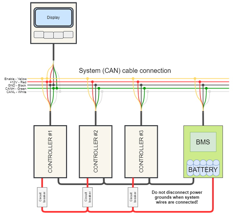
In many legacy vehicle networks, if the master display or VCU dies, the vehicle is bricked. LEVCAN enforces a philosophy of independent yet complementary nodes.
Every device on the bus—whether it is a motor controller, a 16S BMS, an on-board computer, or a smart lighting controller—stores its own configuration in local non-volatile memory and runs its own control loops autonomously:
- A standalone motor controller can regulate total pack voltage on its own.
- The moment a LEVCAN-compatible BMS is plugged into the bus, the controller automatically discovers it and upgrades its protection logic to monitor individual cell voltages and cell temperatures in real time.
- Similarly, the on-board computer scans the bus by device type, aggregates shared metrics onto its main 240×128 LCD dashboard, and exposes each discovered device’s internal parameter tree in a unified configuration menu.
This plug-and-play behavior relies on Dynamic Network Addressing. When a node boots, it claims an address in the 0..124 range and broadcasts its device descriptor and hardware capabilities. If a builder links two, four, or up to eight motor controllers together using passive 4-port CAN splitters—a common architecture in all-wheel-drive scooters, heavy cargo quads, or twin-propeller marine drives—dynamic addressing resolves ID collisions automatically. On the dashboard, the user simply sees 50:Controller, 100:ThermoNucularController, or 31:NucularBMS16S, and can tune each unit independently over a single CAN wire.
Dual Transport Modes: 'UDP' and 'TCP' Over Classical CAN
A standard CAN 2.0B frame carries a maximum of 8 bytes of payload. That is plenty for a 16-bit RPM value and a 16-bit motor temperature, but completely inadequate for transferring configuration structs, string tables, or 100 KB firmware images.
To solve this without forcing application developers to write manual segmentation state machines, LEVCAN implements two distinct transmission modes at the transport layer:
1. 'UDP' Mode (Unacknowledged, Low-Latency Datagrams)
Named by analogy with the IP stack, LEVCAN’s UDP mode is a connectionless, fire-and-forget transport designed for high-frequency cyclic data that fits within small frames or where the newest sample immediately supersedes the previous one.
- Typical Payloads: Real-time throttle/brake ADC voltages, RPM, phase current, bus voltage, and virtual CAN button bitmasks (S1, S2, S3, BK, CR, RV).
- Why It Matters: When a rider pulls an analog or Hall-effect brake lever wired to the handlebar computer, the brake state is broadcast over CAN to all traction controllers and the rear brake-light module simultaneously. There is zero handshake overhead—latency is bounded purely by CAN bus arbitration at 1 Mbps.
2. 'TCP' Mode (Controlled Reception and Strict Data Ordering)
When a node needs to transfer payloads larger than 8 bytes—or when every single byte must arrive intact and in sequence—LEVCAN switches to its TCP transport mode.
- How It Works: The protocol segments arbitrary-length buffers into sequential 8-byte CAN frames, manages flow-control acknowledgments between the sender and receiver, verifies data ordering, and reassembles the complete object in the target node's buffer before triggering the application callback.
- Static vs. Dynamic Memory Allocation: In safety-critical embedded systems (such as a motor controller running a 20 kHz FOC current loop), calling malloc() inside an interrupt or background task is a recipe for heap fragmentation. LEVCAN supports both static and dynamic memory models at compile time. You can configure a bare-metal node to use strictly pre-allocated static ring buffers and message queues, or enable dynamic allocation on larger Cortex-M4/M7 targets running FreeRTOS. Moving LEVCAN onto a queue-driven architecture in recent firmware revisions doubled real-time data-logging throughput while keeping bus timing deterministic.
POSIX/FatFs-Style File Streaming (f_open, f_read) Over a Two-Wire Bus
One of the cleverest engineering features inside LEVCAN is its built-in File I/O and File Server abstraction.
In a typical multi-node EV, adding a microSD card slot, a USB host port, or a Wi-Fi chip to every single peripheral is expensive and mechanically fragile. You do not want an SD card slot exposed to mud and vibration on a compact motor controller tucked inside a swingarm. Instead, you put the microSD slot inside the IP54-rated handlebar On-Board Computer (or connect a laptop via a USB-to-CAN adapter) and designate that node as the network File Server.
Using LEVCAN’s TCP transport layer, any headless microcontroller on the bus can open, read, and write files stored on the remote file server's SD card using standard C functions that mirror FatFs / POSIX semantics:
// Conceptual C11 example: A headless CAN node loading its configuration
// or streaming a firmware block from the On-Board Computer's microSD card over LEVCAN
#include "levcan.h"
#include "levcan_fileclient.h"

void load_remote_profile_over_can(lc_node_descriptor_t *my_node) {
    lc_file_t file_handle;
    uint8_t buffer[128];
    uint32_t bytes_read = 0;

    // Request "ncconf.cfg" from the File Server node on the CAN bus
    if (lc_fopen(&file_handle, my_node, "ncconf.cfg", LC_FA_READ) == LC_OK) {
        while (lc_fread(&file_handle, buffer, sizeof(buffer), &bytes_read) == LC_OK && bytes_read > 0) {
            // Parse configuration parameters into local NVM struct
            apply_config_chunk(buffer, bytes_read);
        }
        lc_fclose(&file_handle);
    }
}
Look at what this abstraction unlocks in practice:
- Single-Point Firmware Updates: Because every device stores its own configuration locally, firmware updates are completely decoupled. A user drops a .bin update package onto a FAT32 microSD card, inserts it into the display, and updates the controller, the display, or the uLight lighting module directly over the CAN wire. By optimizing the underlying LEVCAN queue and block-transfer pipeline, recent controller generations achieved a 6x speedup in CAN firmware flashing.
- Instant Profile Switching from SD Card: Because controllers can call f_open and f_read over the bus, a rider or fleet technician can store multiple .cfg tuning files on the display’s SD card (for example, a 220A track profile for a Talaria MX4 and a restricted street-legal profile) and trigger an instant configuration swap over CAN using a mapped handlebar button.
- Black-Box Telemetry Logging: Headless nodes without local flash storage can stream high-rate diagnostic logs—including phase currents, position sensor data, and Hall sensor error flags—straight to the file server’s microSD card for post-ride analysis.
Developer Workflow: From levcan_objects.h to the uLight Reference Node
An open specification only succeeds if an embedded engineer can clone the repository on a Friday afternoon and have a custom node talking to the bus by Saturday morning.
LEVCAN lowers the barrier to entry in three ways:
Standardized Object Dictionaries (levcan_objects.h)
Instead of forcing developers to guess byte offsets and scaling factors, standard vehicle telemetry and control structures are defined in a single shared C header: levcan_objects.h. Whether your custom PCB is reading pack voltage, subscribing to throttle percentage, or publishing temperature sensor readings, you bind your local C variables to standard object IDs, and every other LEVCAN device on the bus immediately understands them.
Distributed I/O and Self-Describing Parameters (uLight Open-Source Reference)
To show developers how a production node is structured, Nucular published the full source code for uLight (github.com/Nucular-tech/uLight), a CAN-connected lighting, horn, and auxiliary I/O controller.
Studying the uLight firmware demonstrates how a distributed LEVCAN network eliminates physical relays and complex point-to-point wiring harnesses:
- Virtual CAN Ports and Broadcast Inputs: Physical inputs (IO1–IO8 on the display, I1–I13 on the controller, or auxiliary pins on uLight) can be mapped onto standardized virtual CAN button bitmasks (CAN port 1 – CAN port 16) and broadcast across the bus.
- Event-Driven Sensor Broadcasting: Temperature sensor thresholds or input states on a peripheral node like uLight can be published as standard bus events—allowing motor controllers or cooling fans on the network to react to remote sensors without running dedicated thermistor wires back to the main VCU.
- Self-Describing Parameter Trees Over CAN: Because LEVCAN natively supports streaming parameter directories, names, value ranges, and units directly from the target node, a custom device like uLight does not require a bespoke mobile app or a hardcoded menu update on the dashboard. As soon as the node joins the bus, the On-Board Computer or desktop Configurator queries its parameter tree over LEVCAN and renders a live interactive setup menu on the fly.
Built-In Bus Health Diagnostics
Anyone who has debugged a noisy CAN bus in a workshop knows the pain of hunting down a missing 120-ohm termination resistor or a pinched wire. LEVCAN nodes expose low-level CAN controller hardware registers directly to the user interface and diagnostic tools:
- CAN_TEC (Transmit Error Counter) and CAN_REC (Receive Error Counter);
- CAN_OVR (Receive FIFO overrun counter);
- CAN_LEC (Last Error Code), breaking down faults into 1: Stuff Error, 2: Form Error, 3: Acknowledgment Error, 4: Bit Recessive Error, 5: Bit Dominant Error, and 6: CRC Error.
Instead of hooking up a differential oscilloscope probe just to see why a node dropped offline, a technician can read CAN_LEC = 3 (Acknowledgment Error) right on the screen and know immediately that the target node lost power or has a broken transceiver connection.
Bridging Bare-Metal CAN to AI Diagnostics and Coding Agents via REST API (Port 8585)
Modern embedded development is rapidly moving toward AI-assisted debugging, automated fault analysis, and agentic coding workflows. However, an AI coding agent or diagnostic assistant cannot natively talk to a bare-metal 29-bit CAN bus without a translation layer.
Instead of forcing developers to write custom C/C++ DLL wrappers for USB-to-CAN adapters (CandleLight USB, Nucular USB2CAN), the Windows-based LEVCAN Configurator features a modular MEF (Managed Extensibility Framework) plugin architecture (Plugins/ directory for Diagnostics, CANTest, and DebugProbe) that includes a built-in HTTP Loopback Debug Probe API running on http://127.0.0.1:8585 (with interactive documentation at /help).
This loopback server is specifically engineered so that AI coding agents, automated AI diagnostic tools, and local scripts can query live CAN bus data, inspect object dictionaries, and trigger firmware workflows directly over standard HTTP REST calls:
- GET /api/status — Checks the state of the connected CAN adapter and returns the count of active bus nodes.
- GET /api/nodes — Lists all discovered LEVCAN devices currently online (e.g., 100:ThermoNucularController, 31:NucularBMS16S).
- GET /api/telemetry — Captures a real-time telemetry snapshot across the bus (speed, phase/battery current, voltage, controller and motor temperatures).
- GET /api/nodes/{id}/data/{objectId} — Queries standardized LEVCAN objects directly across the CAN bus (such as Temperature, Speed, or DCSupply).
- GET /api/objects?{filter} (also aliased as /v1/models and /api/models for seamless compatibility with AI agent tooling) — Searches the live LEVCAN object catalog.
- POST /api/nodes/{id}/force-update — Triggers a forced bootloader firmware update on a target controller node.
Here is a practical Python example showing how an AI diagnostic agent or automated test script can pull live node telemetry and query specific LEVCAN objects in real time without touching a single line of C:
import requests

BASE_URL = "http://127.0.0.1:8585"

def inspect_levcan_bus_for_ai_agent():
    # 1. Verify CAN adapter link and active node count
    status = requests.get(f"{BASE_URL}/api/status", timeout=1.0).json()
    print(f"[AI Probe] Adapter Status: {status}")

    # 2. Discover all active LEVCAN nodes on the bus
    nodes = requests.get(f"{BASE_URL}/api/nodes", timeout=1.0).json()
    for node in nodes:
        print(f"Discovered Node -> ID: {node.get('id')} | Name: {node.get('name')}")

    # 3. Grab a full real-time telemetry snapshot for automated diagnostics
    telemetry = requests.get(f"{BASE_URL}/api/telemetry", timeout=1.0).json()
    print(f"Live Telemetry Snapshot: {telemetry}")

    # 4. Query specific standard LEVCAN objects from Node 100 (e.g., Controller)
    controller_id = 100
    for obj_name in ["DCSupply", "Temperature", "Speed"]:
        resp = requests.get(
            f"{BASE_URL}/api/nodes/{controller_id}/data/{obj_name}",
            timeout=1.0
        )
        if resp.ok:
            print(f"Node {controller_id} [{obj_name}]: {resp.json()}")

if __name__ == "__main__":
    inspect_levcan_bus_for_ai_agent()
By exposing bare-metal CAN transactions as human- and LLM-readable JSON endpoints (including the /v1/models alias), an AI coding assistant can autonomously read live vehicle telemetry, cross-reference thermal or voltage anomalies against parameter settings, write tuning scripts, and even orchestrate firmware updates directly from the developer's IDE.
The Philosophy of Open Infrastructure: Compete on Silicon, Collaborate on the Bus
Why would a hardware company that spent ten years developing proprietary bare-metal FOC algorithms, 8-layer heavy-copper power stages, and award-winning controllers like the ultra-compact, credit-card-sized Nucular X6F (delivering 10–15 kW of peak output in roughly 227–240g) give away its communication protocol for free under the Apache-2.0 license?
Because in every mature technology sector, communication buses are infrastructure, not a product moat.
Look at the history of personal computing or industrial automation. PC manufacturers did not lose their competitive edge when they stopped inventing proprietary keyboard plugs and agreed on USB and PCIe. Instead, standardizing the bus triggered an explosion of third-party peripherals that made the entire platform far more valuable to the end user.
Right now, the light electric vehicle industry is artificially holding itself back by treating basic packet definitions as trade secrets. When every battery maker, motor controller vendor, and display manufacturer invents a mutually incompatible serial protocol:
- Small OEMs and custom vehicle builders suffer: Instead of focusing on chassis dynamics, industrial design, or suspension geometry, boutique EV startups burn months of R&D budget writing glue code just to make a German BMS talk to an Asian display and a high-power inverter.
- Fleet operators and repair shops get locked out: When a single component fails, diagnostic tools cannot read the bus, turning a $20 repair into a full system replacement.
- Hardware innovation slows down: An independent embedded developer who designs a brilliant new solar MPPT charger, an electronic steering damper, or a custom helmet HUD has no way to integrate it cleanly into a rider's existing cockpit.
By keeping the high-speed motor control loops and thermal hardware competitive while opening up LEVCAN under Apache-2.0, hardware manufacturers and embedded developers get the best of both worlds. A controller can guarantee safety, <1% field failure rates, and sub-millisecond torque control internally, while speaking an open, documented language on the wire.
If you are designing firmware for a custom BMS, building a telemetry node on an STM32, ESP, or architecting the electrical system for a next-generation light EV, stop wiring 20-pin analog harnesses and stop reinventing closed UART parsers. Grab a transceiver, pull the C11 source from the LEVCAN repository (github.com/Nucular-tech/levcan and docs.nucular.tech), and build on a bus that was actually engineered for the vehicles we ride today.
About Nucular
Nucular is a team of engineers and enthusiasts creating electric motor controllers for people who are just as passionate. It's for those who don't accept compromises and want to get the absolute maximum out of their custom electric vehicle. Nucular products are not "black boxes"; they are powerful tools for fine-tuning power, speed, and response. The company believes in the DIY community and gives it full control over its hardware.