

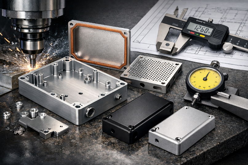
Electronics enclosures do more than protect internal components. They play an essential role in managing heat, maintaining electromagnetic compatibility, and ensuring that circuit boards and other components fit accurately during assembly. For engineers and product development teams, selecting the right manufacturing process is critical to achieving reliable performance, consistent quality, and cost-effective production.
CNC machining is a widely used manufacturing solution for electronics enclosures that require dimensional accuracy, effective electromagnetic interference (EMI) shielding, and durable surface finishes. From material selection and tolerance control to electrical contact requirements and finishing processes, several engineering considerations influence the performance of a finished enclosure.
This article examines the key factors involved in CNC machining for electronics enclosures and explains how thoughtful design and manufacturing decisions can improve product reliability, assembly accuracy, and production efficiency.
Why CNC Machining Is Suitable for Electronics Enclosure Production
Electronics enclosures must satisfy several functional requirements simultaneously. Mounting points, connector openings, and covers need to align accurately during assembly. At the same time, the enclosure must provide appropriate protection against electromagnetic interference (EMI), environmental exposure, wear, and corrosion.
CNC machining addresses these requirements through computer-controlled material removal. It enables manufacturers to produce precise pockets, mounting holes, threaded features, and complex internal geometries with consistent accuracy.
Unlike injection molding, CNC machining does not require expensive mold tooling, making it a practical option for prototypes and low-volume production. Compared with conventional sheet metal fabrication, it also offers greater flexibility when manufacturing solid, three-dimensional features and complex enclosure designs.
LKprototype provides CNC machining services for electronics enclosure projects, supporting prototype development and low-volume manufacturing through design-for-manufacturability (DFM) reviews and ISO 9001:2015 quality management processes.
Key advantages of CNC machining for electronics enclosures include:
- Dimensional accuracy: General machining tolerances of ±0.05 mm are achievable, while tighter tolerances can be specified for critical features when required.
- Material versatility: Aluminum, stainless steel, copper, brass, and engineering thermoplastics can be machined to meet different application requirements.
- Design flexibility: CAD model revisions can be incorporated without manufacturing new molds, helping simplify product development.
- Assembly consistency: Precisely machined holes, pockets, and mating surfaces help minimize alignment problems and improve component fit.
For companies developing electronic products, these capabilities support faster design validation, reliable assembly, and more predictable manufacturing outcomes.
Material Selection for CNC Machined Electronics Enclosures
Material selection directly affects an enclosure's EMI shielding performance, thermal management, weight, durability, and manufacturing cost. Three material categories are commonly considered for electronics enclosure applications.
Aluminum Alloys
Aluminum is one of the most widely used materials for electronics housings. Alloys such as 6061 and 6063 offer a useful combination of mechanical strength, low weight, thermal conductivity, and corrosion resistance. Their electrical conductivity also makes them suitable for many EMI shielding applications.
Thermal management is another important advantage. Power supplies, motor controllers, and high-density circuit boards generate heat during operation. Aluminum enclosures can help transfer this heat away from sensitive components, supporting more stable operating temperatures and long-term product reliability.
Stainless Steel
Stainless steel is often selected for enclosures exposed to demanding operating environments, including chemical processing facilities, washdown areas, and certain outdoor or industrial applications. Its corrosion resistance, mechanical strength, and durability make it suitable for applications where environmental protection is a priority.
However, stainless steel is heavier and generally more difficult to machine than aluminum. These characteristics can increase machining time and overall production costs. Its EMI shielding effectiveness also depends on the material grade, frequency range, and specific electromagnetic requirements of the application.
Engineering Plastics and Hybrid Designs
Polycarbonate and other engineering thermoplastics are useful when lightweight construction, electrical insulation, and impact resistance are important. They also provide flexibility in enclosure design.
However, plastics generally offer little inherent EMI shielding. Applications requiring electromagnetic protection may need conductive coatings, metallized surfaces, or integrated metal shielding components.
Hybrid designs provide another practical option. Combining a machined aluminum frame with plastic covers or panels can balance weight, cost, electrical insulation, and shielding requirements.
EMI Shielding: Design Principles and Machining Strategies
Electromagnetic interference can affect signal quality, disrupt electronic communication, and cause sensitive components to operate incorrectly. Effective EMI shielding depends on several factors, including material conductivity, enclosure geometry, electrical continuity, and the quality of joints and seams.
Conductive Materials and Enclosure Integrity
Materials such as aluminum and copper provide conductive barriers that reflect and absorb electromagnetic energy. Stainless steel can also provide shielding, although its effectiveness varies depending on the application and operating frequency.
For an enclosure to provide effective shielding, electrical continuity must be maintained across its joints and seams. CNC machining helps achieve this by producing accurately fitted edges, overlapping surfaces, and precise mating features.
These details help minimize unwanted gaps that could allow electromagnetic interference to enter or escape the enclosure.
Wall Thickness and Gap Control
Wall thickness influences shielding performance, but increasing it does not necessarily produce a proportionate improvement. Thicker walls can increase material consumption, enclosure weight, and machining time.
A more effective approach is to select wall thickness according to the enclosure's operating requirements, available space, and shielding targets.
Gap control is equally important. Small openings around covers, connectors, and joints can affect shielding effectiveness. CNC machining allows manufacturers to maintain accurate mating surfaces and fastener positions, helping enclosure components fit together consistently.
Grounding Features
Proper grounding helps manage unwanted electrical currents and supports electromagnetic compatibility. CNC machining makes it possible to integrate grounding points, contact pads, mounting surfaces, and other electrical connection features directly into an enclosure.
Planning these features during the initial design stage can reduce the likelihood of costly modifications after testing.
Surface Finishes and Shielding Performance
Surface treatments can influence electrical conductivity and contact resistance. Conductive finishes such as nickel plating, tin plating, and suitable conversion coatings may help maintain electrical contact between mating surfaces.
Anodizing improves aluminum's corrosion resistance but creates an electrically insulating oxide layer. For this reason, grounding points and electrical contact areas may need to be masked or treated separately.
Similarly, powder coating and paint should be kept away from surfaces that require direct electrical contact. Considering these requirements during the design stage helps prevent finishing processes from interfering with the enclosure's shielding performance.
Tolerance Allocation in Electronics Enclosure Machining
Tolerance selection affects component alignment, enclosure fit, shielding performance, assembly time, and manufacturing cost. If tolerances are too loose, covers may not fit properly, and unwanted gaps may develop around critical joints. On the other hand, unnecessarily tight tolerances can increase machining time and inspection costs without providing meaningful functional benefits.
Typical Tolerance Ranges
Depending on the manufacturing process, material, geometry, and supplier capabilities, electronics enclosures may use tolerance ranges such as:
- ±0.10 mm: General features and non-critical dimensions.
- ±0.05 mm: Mating surfaces and component mounting areas.
- ±0.01 mm: Selected critical features where the design and manufacturing process support this level of precision.
These values are application-dependent examples rather than universal machining standards. Actual tolerances should be confirmed with the manufacturing partner during the design review.
Tight tolerances should only be specified where they serve a clear functional purpose. Applying ±0.01 mm across every dimension can increase production costs without necessarily improving enclosure performance.
Critical Tolerance Zones
Some areas of an electronics enclosure require greater dimensional control than others.
Seams and mating surfaces influence EMI shielding, while mounting holes and PCB standoffs determine component alignment. Connector openings must also match the dimensions and positioning of external interfaces.
Identifying these critical areas early allows engineers to allocate tolerances more effectively and avoid unnecessary manufacturing costs.
Achieving Consistent Machining Precision
Modern CNC machining centers, including multi-axis platforms, can produce complex enclosure geometries with consistent dimensional accuracy. However, reliable results depend on more than advanced machinery.
Process control is equally important. Monitoring tool wear, maintaining stable setups, and inspecting finished components help ensure that production parts remain consistent with the original design specifications.
Design-for-manufacturability (DFM) reviews also play an important role. Standard drill sizes, practical corner radii, and reasonable pocket depths can simplify machining and reduce production costs.
Sharing CAD files with the manufacturing partner early in the development process allows potential manufacturing challenges to be identified before production begins.
Surface Finishes: Function, Durability, and Appearance
Surface finishing influences an enclosure's appearance, corrosion resistance, wear performance, and electrical properties. The most appropriate finish depends on the base material, operating environment, and functional requirements of the finished product.
Anodizing
Anodizing strengthens the natural oxide layer on aluminum, improving corrosion resistance and surface hardness. It also provides different color options, making it useful for products where appearance and identification are important.
For electronics enclosures requiring electrical grounding, contact areas may need to be masked because standard anodizing creates an electrically insulating surface layer.
Powder Coating
Powder coating creates a durable protective layer available in different colors and surface textures. It offers good resistance to scratches, environmental exposure, and certain chemicals.
This finish is suitable for many industrial and outdoor enclosures. However, coated areas should be excluded from surfaces that require direct electrical contact.
Bead Blasting
Bead blasting creates a consistent matte appearance by treating the component with fine abrasive media. It helps reduce the visibility of minor machining marks and can prepare surfaces for additional finishing processes, including anodizing.
Because it generally involves limited material removal, bead blasting can be useful for components where maintaining dimensional accuracy is important.
Plating
Nickel and tin plating can provide conductive surface layers while improving corrosion resistance. These finishes are particularly useful for enclosure components where reliable electrical contact between mating surfaces is required.
The selected plating process should be compatible with the base material and the enclosure's operating environment.
Finish Selection Criteria
Choosing the right finish requires balancing functional and aesthetic requirements.
Electronics enclosures used for sensitive equipment may prioritize electrical contact and thermal performance. Medical and industrial applications may require finishes that withstand regular cleaning and environmental exposure, while consumer products often place greater emphasis on appearance and color consistency.
Production volume, processing time, and finishing costs should also be considered when selecting a suitable surface treatment.
Design Guidelines for CNC Machined Electronics Enclosures
Good enclosure design can simplify machining, reduce production costs, and improve long-term reliability. Applying several practical design principles during the development stage can help engineers achieve better manufacturing results.
1. Add fillets to internal corners.
Sharp internal corners can be difficult to machine with standard cutting tools. Adding suitable radii, such as 1.5 mm where the design permits, can improve tool access and reduce unnecessary machining complexity.
2. Maintain reasonable pocket depths.
Deep pockets may require longer cutting tools and additional machining operations. Features with depths greater than approximately six times the tool diameter should be reviewed to determine whether alternative geometries or machining strategies would be more practical.
3. Specify tolerances deliberately.
Apply general tolerances to non-critical features and reserve tighter specifications for functional interfaces, mounting points, and mating surfaces. This approach helps maintain accuracy without increasing manufacturing costs unnecessarily.
4. Plan EMI shielding features early.
Grounding points, conductive contact areas, seam overlaps, and wall thickness requirements should be considered during the initial design stage rather than added after electromagnetic compatibility testing.
5. Review the design with the manufacturing partner.
A DFM review can identify difficult features, unnecessary complexity, and potential manufacturing issues before production begins. Early communication also helps engineers evaluate material options, machining limitations, and finishing requirements.
Conclusion
CNC machining offers a flexible and reliable manufacturing approach for electronics enclosures that require dimensional accuracy, effective EMI shielding, and durable surface finishes. Selecting suitable materials, planning electrical contact points, allocating tolerances carefully, and choosing appropriate finishing processes all contribute to the performance and reliability of the finished product.
For engineering teams developing prototypes or preparing for low-volume production, working with an experienced machining partner early in the design process can help identify potential challenges, improve manufacturability, and maintain consistent production quality.
LKprototype supports electronics enclosure projects with CNC machining, DFM assistance, and quality-focused manufacturing processes. By considering material selection, shielding requirements, machining tolerances, and surface finishing from the beginning, product development teams can create enclosures that meet their functional requirements while keeping manufacturing practical and cost-effective.