
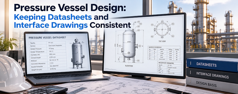
Pressure vessel design packages can contain neatly formatted files and still describe incompatible equipment. When a datasheet mismatch puts an outdated duty beside current interface drawings, the fabricator is left to discover which description governs and whether the apparent agreement between the remaining files rests on a shared but obsolete assumption. Pressure vessels need connected engineering inputs. Process conditions, geometry, connections and assessment requirements must agree.
Technical teams accustomed to versioned digital files will recognise the underlying problem. A file can be current within its own folder while referring to an obsolete interface elsewhere. Document control helps expose that inconsistency, but drawing software does not validate pressure-equipment engineering. The design package becomes useful when its related documents describe the same accepted configuration.
What pressure vessel design has to resolve
Containing fluid under specified conditions is the vessel's basic task, while its connections and internal features allow it to perform a process function within the chosen arrangement and connect to the surrounding plant through a set of agreed interfaces. Design extends beyond the shell outline.
Datasheets describe requirements concisely. Drawings show how the proposed equipment meets the relevant physical requirements. Neither can substitute for the engineering work that establishes suitability. Precisely drawing an unsuitable configuration still leaves the wrong basis for manufacture.
Begin by assigning an owner to each unresolved input. Process engineers may need to clarify fluid conditions while installation colleagues confirm space and connection constraints, giving the fabricator an agreed basis that reflects the decisions of everyone responsible for the equipment's intended service. Acceptance is a technical decision. Changing a document's status cannot make it.
Datasheets connect duty to the vessel configuration
ChannelVessel asks for working and design pressure and temperature, fluid and corrosion conditions, capacity and material grades when discussing custom equipment. It also requests drawings and process information, so the enquiry includes both the duty and the proposed physical arrangement.
Working conditions describe intended operation, whereas design pressure and design temperature are engineering inputs that must be agreed for the applicable design basis. Copying an operating value into another field without review can conceal a missing decision. Where more than one credible condition matters, the responsible engineer should explain which combinations govern.
For reactors, connect those inputs to the intended process stages and the proposed heating or cooling arrangement. Changing the process medium can also affect the material review. Check meaning, not just completed fields. Do the recorded conditions still describe the same intended service?
The P&ID explains connections by function
Piping and instrumentation diagrams, usually called P&IDs, represent process connections and instruments by their function in the system, explaining what a connection is intended to do without establishing the physical location, orientation or accessible space around every nozzle on the vessel. Function and geometry need separate descriptions.
Follow each vessel connection from its process function to the corresponding physical drawing. A vent shown in the process diagram needs an identified vessel connection; a drain shown in the layout needs a clear relationship to the intended drainage function. Resolve unnamed or inconsistent connections before the design moves into fabrication.
Process skids make this mapping especially useful because vessels share a package with piping and instruments. Package drawings can look complete while a connection responsibility remains open at the boundary. Ask who supplies the mating component and who approves the interface so diagram completeness does not disguise an installation question.
A nozzle schedule turns intent into interfaces
The public enquiry guidance from ChannelVessel asks purchasers to specify nozzles, manways, drains, vents and instruments, together with orientation, space restrictions and interfaces. These details connect a pressure vessel's intended functions to the physical features that must appear in its drawings.
Nozzle schedules give connections stable identities and record their agreed characteristics. Match the schedule to both the vessel drawing and process diagram. If a connection changes location, the attached pipework and access requirements may also need review even when the nozzle's identifying tag remains unchanged.
Do not use a matching tag as the only consistency test. Compare function, location and the agreed connection details, then check the mating interface. Ask the relevant engineer to resolve discrepancies explicitly. For replacement pressure vessels, verify the current installation rather than assuming an old drawing still represents the equipment and pipework found on site.
Heat exchangers need clearly separated duty descriptions
Heat exchangers introduce distinct fluid paths into the design package. Specify which conditions and connections belong to each side. General notes about the process fluid cannot safely stand in for a description of the entire exchanger, including its utility connections and maintenance arrangement.
Carry that separation through datasheets, connection schedules and interface drawings. Where a duty changes, review the affected path and its related interfaces. Revised utility requirements may involve a different connection or operating assumption even if the main process description has not changed.
Consistency supports engineering review; it cannot perform it. Matching values across files shows that the descriptions agree, without establishing that the selected construction will deliver the intended thermal duty or meet the pressure design basis accepted by the project. Obtain those engineering decisions through the agreed supplier review process.
Reactors bring internal features into the revision review
Reactors may combine containment with agitation and heating or cooling. Their external outline can remain familiar while an internal component changes the process arrangement or maintenance task. Reviewing only the vessel envelope can therefore miss a consequential revision.
ChannelVessel lists reactors and requests details of jackets, coils, agitators and internals for custom enquiries. When considering ChannelVessel drawing-based fabrication, include these features in the same review as the datasheet and connection schedule. Compare the selected configuration with actual process requirements; finding an accessory name somewhere in the files does not complete that review.
Ask which drawing describes each internal feature and what other documents depend on it. Alterations can affect access, removal space or adjacent connections. Document the decision at the affected interface so an approved internal change does not leave an older installation assumption in circulation.
Document changes must follow physical consequences
Writing “nozzle moved” records an edit but says little about its consequences, which may extend into attached piping, nearby structures or maintenance access even when the revision looks minor on the vessel drawing. Follow the physical relationships. File approval is only part of that work.
Use the proposed configuration as the reference during a coordinated review. Compare its datasheet, P&ID, nozzle schedule and arrangement drawing, then identify any dependent documents requiring action. Close contradictions that matter to fabrication and installation. Identical wording is unnecessary.
Some changes affect only drafting clarity; others alter a technical requirement. Ask the responsible engineer to distinguish them. Record which assumptions remain valid and who accepted the change. If manufacture has started, establish the actual fabrication status before treating a newly issued drawing as an instruction that can be implemented without further assessment.
Construction-code scope is a separate design input
ASME's published pressure-vessel construction scope addresses design, fabrication, inspection, testing and certification for internal or external pressure exceeding 15 psig. That scope description does not establish a particular supplier's certification.
Projects still need an agreed construction basis and any destination-specific requirements that apply. Naming a standard in a quotation does not identify every required examination, record or acceptance responsibility. Keep those requirements connected to the technical package rather than isolated in a commercial note that the drawing reviewers never see.
Before drawing release, ask how the agreed requirements appear in the supplied documents and which evidence will accompany the completed equipment. If a requirement changes, review its effect on the design and fabrication plan. Record an explicit technical disposition. Updated title blocks cannot settle technical questions.
Release a coherent package for fabrication
Keep the final review short enough to use and specific enough to expose a real mismatch. Walk through a representative connection and its duty, then extend the same checks across the vessel's affected interfaces:
- Confirm that datasheets describe the accepted fluid conditions and design basis.
- Match process functions on the P&ID to entries in the nozzle schedule.
- Check connection locations against the installed arrangement and mating equipment.
- Include internal features and their maintenance requirements in the review.
- Identify unresolved changes, their decision owners and the documents they affect.
Fabrication readiness means the supplier can build from a consistent set of accepted requirements. Open engineering questions need answers, even inside an approved folder. Reviewers should be able to follow a duty from the datasheet to the physical feature without discovering a contradictory revision on the way.